This is part three of my attempt to build the original Kickstarter version of the Pimorini Picade (Maxi version). Part two is here.
As we left off, I was getting ready to work on the wiring loom…

I’m now tasked with wiring all of the buttons on the cabinet, as well as everything on the control panel. It’s relatively easy once you sort through all the wiring looms. You just have to have one ground for every active plug, and each section has two pins.

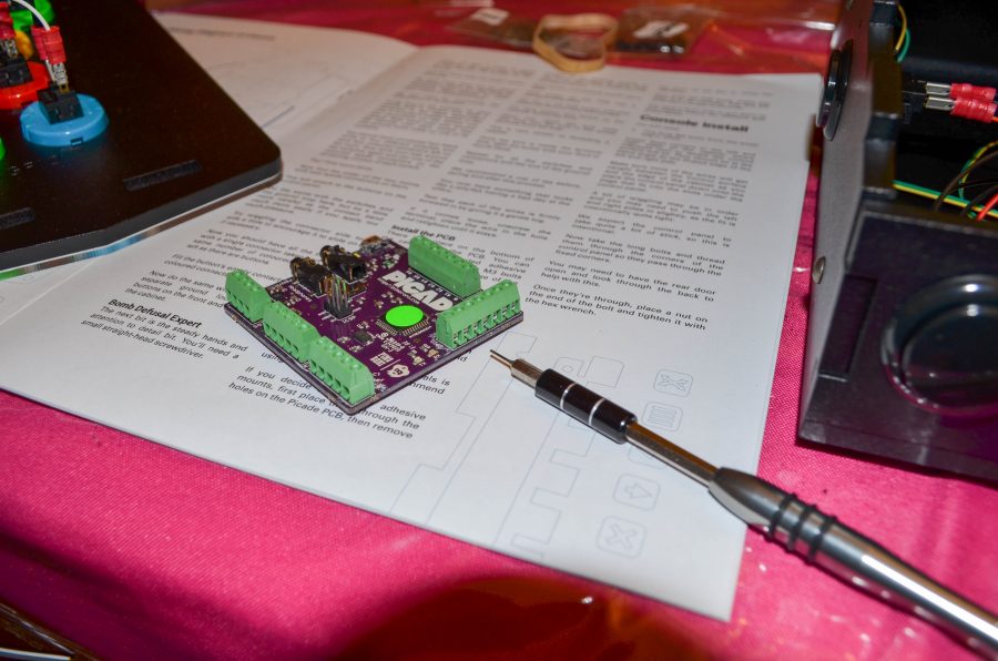
This is the PCB. I need to loosen all of the screws in order to insert the wires. It actually came with a small screwdriver, but I didn’t see it, so I used my own.

I struggled mightily getting the wires into the holes and locking the wires down. I ended up having to strip some to reveal additional wire for the ones that I damaged. I eventually figured out that if I slightly looped the end of the wire, I could get it to stay better. Hopefully this technique allows everything to work the way that it should.

In terms of difficulty and frustration on this project, I’d put this wiring at the top. As you can see, however, I did get it done finally.

It was difficult connecting the wiring from the control panel buttons to the PCB (I didn’t state it before, but everything goes to a specific place on the PCB), but I eventually got that as well. I also attached the speakers, referring to the manual to remember which was the left speaker and which was the right speaker. As stated earlier, the further I get in the manual, the less detail they seem to go into.

I used the included sticky tape and plastic bolts to secure the PCB. You can also screw it in, but that was too difficult.

Next, I secured the control panel. That involved screws and bolts and access from the rear panel.

Now I had to secure the LCD panel’s controls.

The LCD panel’s control panel lines up with the holes on the outside of the cabinet.

I then applied the sticky exterior buttons. It works really well.

I attached all of the remaining wires before connecting the CPU (in this case, a Raspberry Pi 2).
The next steps are going to be the big finish. I need to configure RetroPie on a microSD card, then insert that into my recently received Raspberry Pi 2 Model B. Then I hook everything up and see what works and what doesn’t (hopefully my wiring is OK). Of course, there’s going to be a lot of additional configuration with RetroPie and the Raspberry Pi 2 Model B in general. This part is definitely not going to be plug and play, and will likely rank highly on the frustration scale. Until next time…
Read the rest of the series:


 Your total news and information resource for all things Science, Technology, Engineering / Mathematics, Art, and Medicine / Health.
Leave a Comment